Apollo Manual Call Point Wiring Diagram
The base is designed to operate over a voltage range of 9v to 15v dc. The manual call point signals to the control and indicating equipment using an interrupt feature within the.

Apollo 65 Wiring Diagram
Introducing a new enhanced parental leave policy providing 14 weeks paid leave for all staff as part of our commitment towards creating a more diverse and inclusive culture here at apollo, we are proud to announce our parent company, halma's new paid parental leave initiative to help our employees with their growing families.
Apollo manual call point wiring diagram. Apollo 1050 gate opener manual; These detectors have been carefully researched and developed by the apollo design team and the range has undergone rigorous testing to ensure A tough transparent polycarbonate shield and frame that fits over a manual call point with.
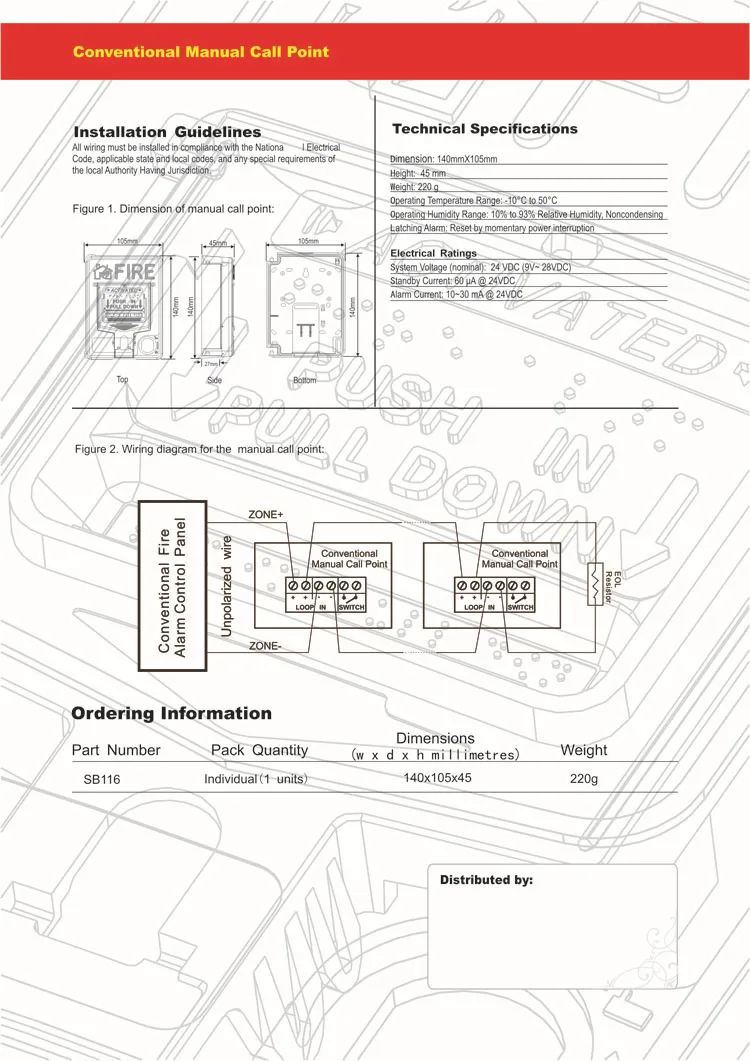
Manual call point pushbutton and break glass stations installation and maintenance instructions safety messages to installers and users it is important to follow all instructions shipped with this product. As mavili elektronik, we have gathered common problems in the field and solutions of these problems. This instruction manual serves as a guide for the apollo series.
Electrical description the detector is designed to be connected to a two wire. An alarm is initiated by pressing the resettable element. The conventional manual call point has been designed to operate on conventional fire detection systems, the manual call point is available in two versions, indoor and outdoor in.
Page 1 xp95 engineering product guide ionisation smoke detector optical smoke detector heat detector multisensor detector manual call point isolating base sounders. Wiring diagram manual call point. This call point station is to be installed by a trained electrician who is.
Orbis is is a demonstration of apollo's commitment to the market for. The 12v relay base is operated by the detector and must therefore be fitted with a series 65 smoke or heat detector to function. Continuity link for wiring test before commissioning.
Orbis is comprises an optical smoke detector,. Notify me when this product is available: Api manual of petroleum measurement standards chapter 3;
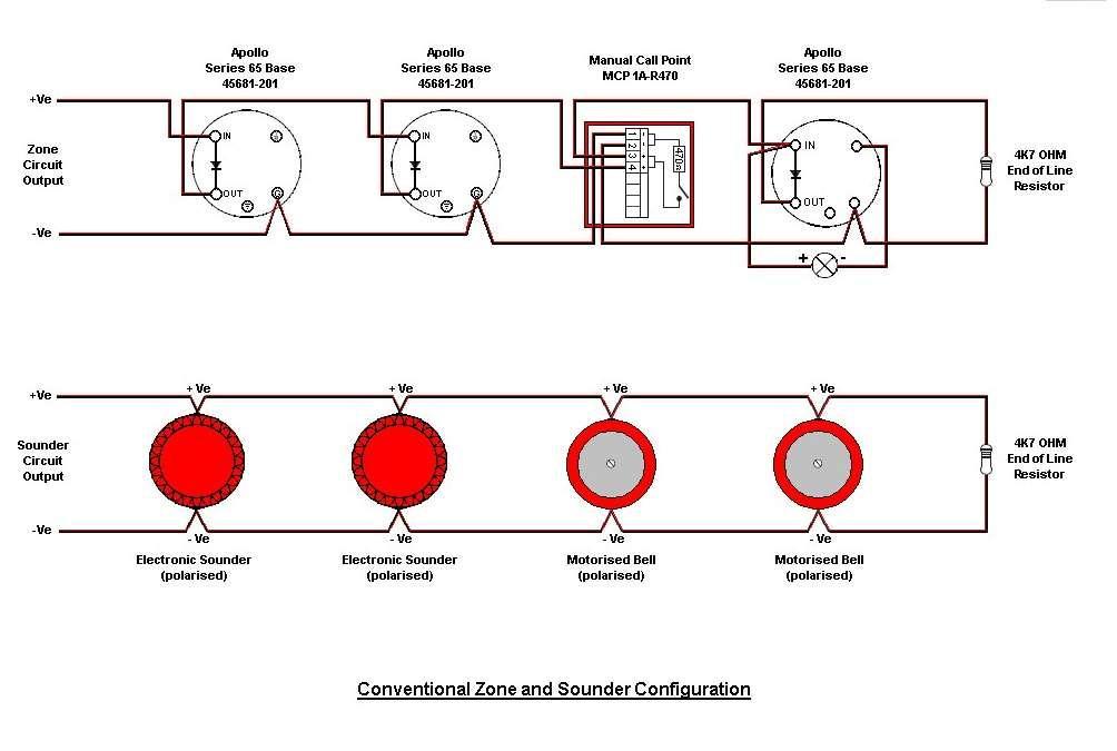
Summary of contents of user manual for apollo xp95. Call points are installed at 1.4 meter above the floor level for ease access in case of emergency. Conventional manual call point wiring diagram soup io, apollo 65 base wiring diagram 2000 honda civic ac nissan, xp95 discovery mounting bases apollo fire, xp95 engineering product guide henry, installer s wire guide fire alarm resources, conventional fire alarm systems typical wiring diagram, addressable 96db a base sounder c tec,
A manual call point, isolator, loop sounder and other compatible products are also available. Apollo orbis smoke detector wiring diagram. Aplus accounting software user manual;
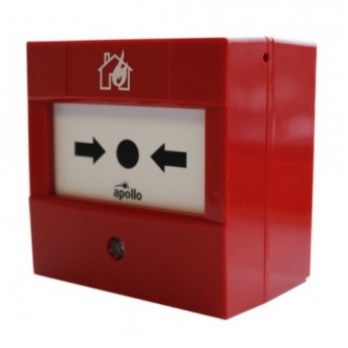
Please read through all provided instructions and any listed warnings in regards to product use. Xfp apollo/hochiki addressable fire alarm systems. A fire alarm manual call point (also known as break glass point) is a device which is used to trigger the alarm circuit by breaking the glass and pressing a frangible element in case of emergency or fire.
Page 2 the xp95 range of intelligent fire detectors is advanced in design, improved in performance and has unique features that. Apollo series 65 relay base wiring diagram. • be aware of all moving parts and avoid close proximity to any pinch points.
The intelligent manual call point has been designed to operate on a loop of intelligent fire detection devices. Apexi safc 2 installation manual; Apollo cloud 2 duo manual;
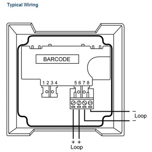
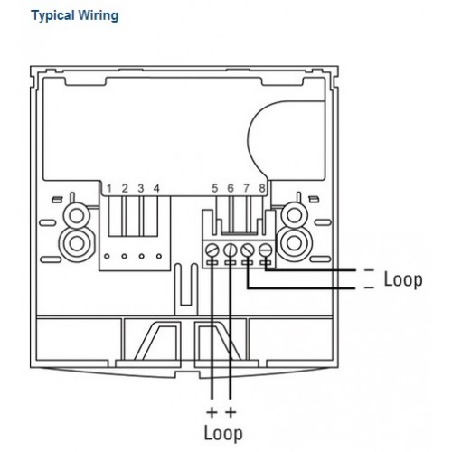
The mcp can be quickly tested and reset using the. 'plug and play' terminal connections for faster wiring. The alarm relay will reset on a 'silence alarms' signal from the control panel.
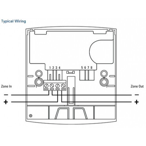
Positive zone wiring connects to com 2 and the negative to com 1. Below is a list of tools necessary for installation of the 816 actuator: Apollo manual call point wiring diagram;
Suitable for semi flush or surface mounting. The negative line is connected to the l1 in and l1 out on the moulding terminals. Apollo has reached a leading position in the market for.
The manual call point is used to manually initiate an alarm signal on the fire detection system. Fig.2 diagram showing lines of equipotential for the xp95 ionisation smoke monitor page 6.

Apollo XP95 resettable manual call point, call points, alarms, 55100905 UK
Break Glass Wiring Diagram
Break Glass Wiring Diagram

KAC Breakglass Call Point Installation Instructions Manualzz

Fulleon Call Point Wiring Diagram

55100001 Apollo Series 65 Manual Call Point Fire Trade Supplies

️Apollo Xp95 Smoke Detector Wiring Diagram Free Download

Apollo 65 Wiring Diagram

Arindam Bhadra Fire Safety Fire Alarm Addressable Manual Call Points

Apollo 65 Wiring Diagram
Apollo Orbis Smoke Detector Wiring Diagram
Break Glass Wiring Diagram

Optical Smoke Det Activ En547 Wiring Diagram Ctec ActiV Optical Smoke Detector (C4416) JK
Break Glass Wiring Diagram


Apollo Manual Call Point Wiring Diagram
Fire Alarm Manual Call Point Wiring Diagram blogmaygomes
Apollo Series 65 Conventional Manual Call Point 55200001APO

Fulleon Call Point Wiring Diagram
Protec 3000/MCP Manual Call Point