10r 02 7026-27 Relay Wiring Diagram
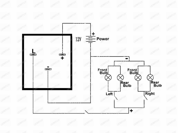
12v 40a relay 4 pin wiring diagram. As in the diagram a wire is run from a 12 volt power source to the switch in the cab and out to the relay placing a fuse at the source of the power.
Dozens of the most popular 12v relay wiring diagrams created for our site and members all in one place.

10r 02 7026-27 relay wiring diagram. At least it is different from my front harness of a dec built 66 ss from flint and a nov built 66 327 with ac from kansas city. 66 chevelle ss396 & 66 chevelle 327 convertible. I think that the 66 diagram post is wrong for some 66 chevelle's.
A normally closed relay will switch power off for a circuit when the coil is activated. The square relay pinout shows how the relay socket is configured for wiring. The interior mounted switch only draws minimal power though the interior fuse block to activate the relay.
Not merely will it help you attain your desired results quicker, but also make the complete procedure less difficult for everybody. • spdt through 4pdt † ac or dc operated † horsepower rated h rs41 and rsd41 relays have a b300 rating. I cover 34 and 5 pin relays and all you need is a 12v source a multimeter and a test light.
It is applicable on both split phase and capacitor start motors. They can be used as a guide when wiring the controller. Wiring diagram comes with a number of easy to follow wiring diagram guidelines.
A normally open relay will switch power on for a circuit when the coil is activated. This list covers single pole single throw (spst) relays, single pole double throw (spdt) relays, and double pole double throw (dpdt) relays. 5 pin relay 5 pin relays provide 2 pins (85 & 86) to control the coil and 3 pins (30,.
Then run a heavy gauge wire from the battery to the relay placing a 30 amp. They show the relative location of the components. Bosch type relay wiring diagrams.
Zone valve wiring diagrams boiler wiring diagrams wiring for 4 wire zone valve low voltage 120 volts 120v 24v boiler connections t 1 t 2 3 zone valve hot neutral wiring for zone valve (follow the relay's wiring schematic when connecting the wires to the relay) one of the relays terminals goes to ground. It really is meant to assist all the common person in creating a correct system.
The main difference is in the radiator support junction box and the alternator/horn relay area. Here is a picture gallery about 12v relay switch wiring diagram complete with the description of the image, please find the image you need. The 3cr relay can be mounted directly on the motor housing or at a convenient location away from the motor.
See below for an example of a relay wiring diagram. We hope this article can help in finding the information you. Automotive relay diagram relays relays are switches controlled by electrical power, like another switch, computer or control module.
An online repository here of things like scans of no longer available diagrams and manuals will hopefully in the future be a reality. Each of the different types of relays have different configurations (as they have different numbers of pins). The real benefit behind a.
I have both diagrams but they dont copy or scan good enough to use. The iso mini relay we have looked at above has 4 pins (or terminals) on the body and is referred to as a make & break relay because there is one high current circuit and a contact that is either open or closed depending upon whether the relay is at rest or energised. Wiring with a relay allows the power to run straight from the battery, through the relay mounted nearby, directly to the lights.
Below are the diagrams for connecting the various types of relays. In the following example diagrams, various applications are shown and many applications can be done according to the operating voltage, power, number of contacts, animated gif relay. The purpose of a relay is to automate this power to switch electrical circuits on and off at particular times.
The compact size of these relays makes them ideal for downsizing equipment. The relay features a plastic housing with mounting tab for easy installation. The top portion of the receptacle is not controlled by the 20 a receptacle control relay module, while the
The first scheme does not apply the single contact relay energy, the upper motor is running, the relay is running, the lower motor is running. If the contact is broken with the relay at rest then the relay is referred to as normally open (no). Here is a video on how you can test a relay with or without a diagram.
Switching relay wiring diagrams zone 1 zone 2 zone 3 fuse 1 amp z one 1 zone 2 zone 3 power zone 1 zone 2 n p zc h x1 x2 r com / 24 vac. Free download with regard to 12v 30 amp relay wiring diagram by admin. These directions will be easy to understand and implement.
Electrical wiring diagrams throughout 12v relay switch wiring diagram, image size 650 x 650 px, and to view image details please click the image. If you need a relay diagram that is not included in the 76 relay wiring diagrams shown below, please search our forums or post a. Buy relays, pigtails, and kits here.
With such an illustrative guide, you'll be capable of troubleshoot, stop, and complete your tasks easily.
Кнопка CE4T10R02 аварийного останова с фиксацией 2НЗ отпускание поворотом 40мм Кнопки
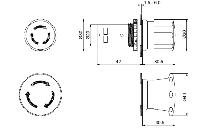
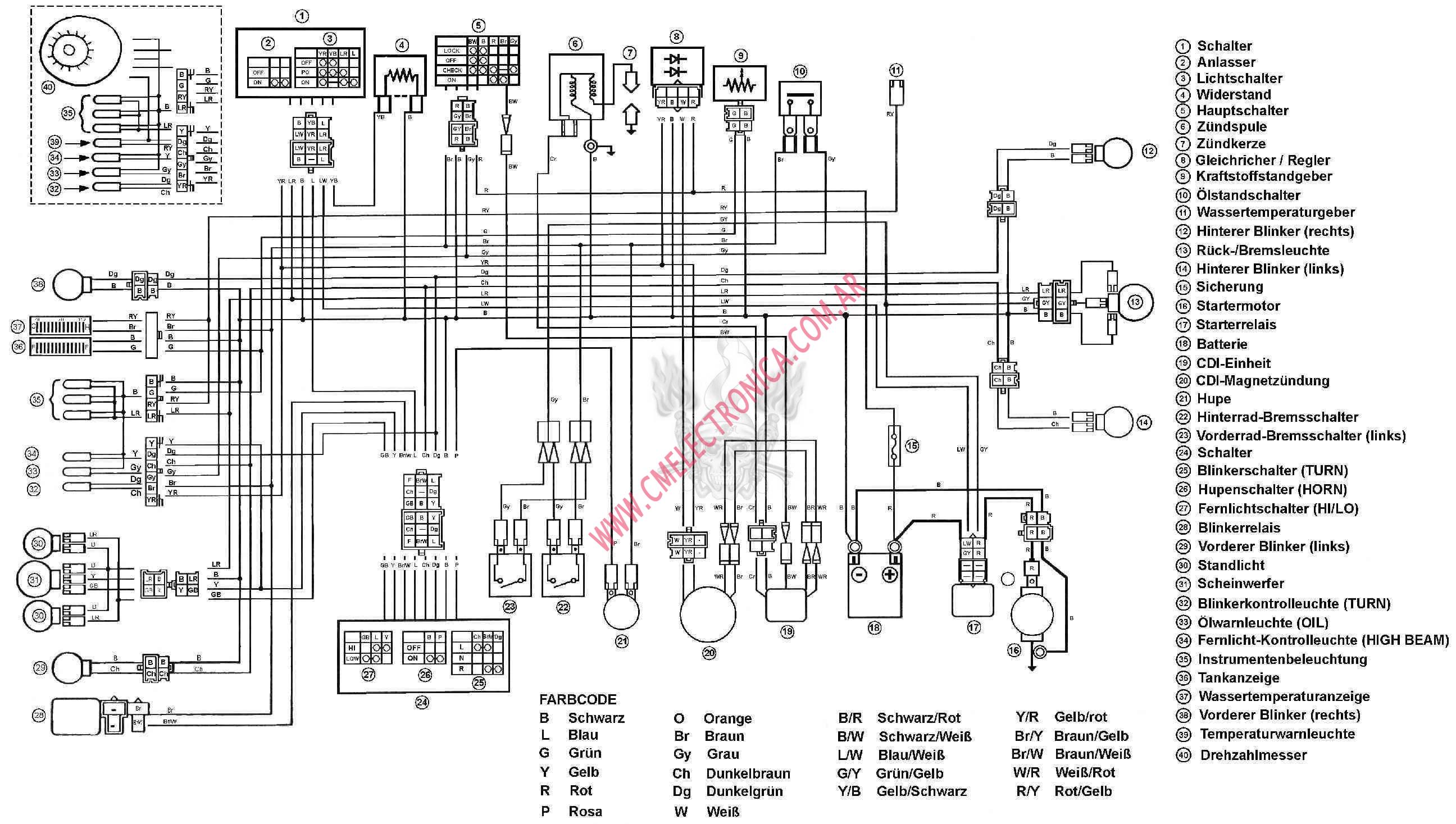
Diagrama yamaha aerox nitro
44090 5 Pin Flasher, Electronic LED, ISO Terminals
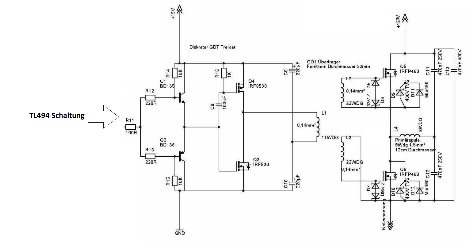
Wie Risetime vom Tl494 verschnellern
index

Zx9R Wiring Harnes 1998 1999 Kawasaki Zx9r Oem Main Engine Wiring Harness Motor Loom 98

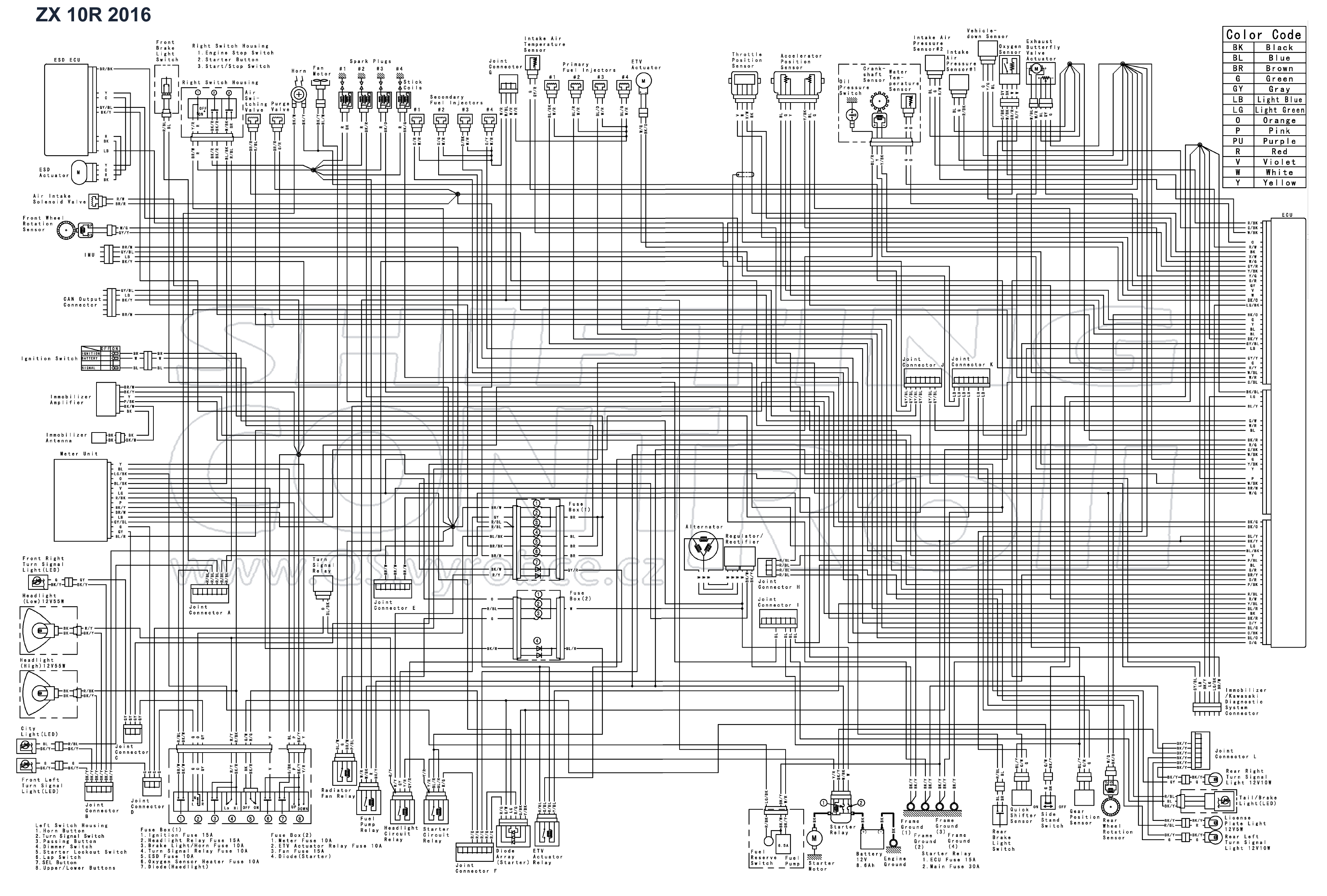
22+ Wiring Diagram On 05 Zx10R

Kawasaki Motorcycle 2018 OEM Parts Diagram for Rear Wheel / Chain

[WB_4643] Versys 650 Wiring Diagram Schematic Wiring

KAWASAKI ZX10R ZX 10R 1000R 1000 WIRING HARNESS 06 07 K108 eBay
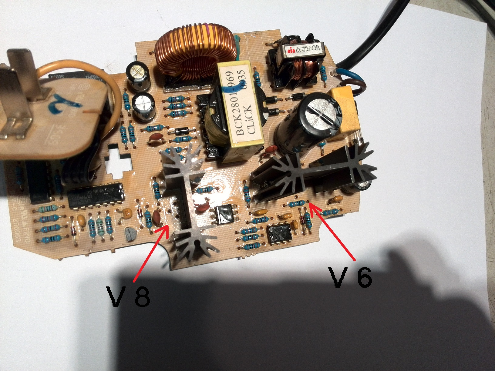
V6 P5NK80Z
lm386 amp circuit problem
3Pin EP28 Electronic LED Flasher Relay Fix Turn Signal Bulbs Hyper Flash Issue eBay
2008 Zx10r Headlight Wiring Diagram Wiring Diagram and Schematic
Speedo Healer Help Page 3 Kawasaki
scorpion alarm wiring diagram Wiring Diagram
Practical LED Indicator And Flasher Circuits Nuts & Volts Magazine

Basit bir boost converter tasarımı Sayfa 4