Securitron Key Switch Wiring Diagram
Door position switches, or dps, are used to detect the open or closed status of a door relative to its frame and then relay this status to a control panel. 7 ampere rated spdt switch.

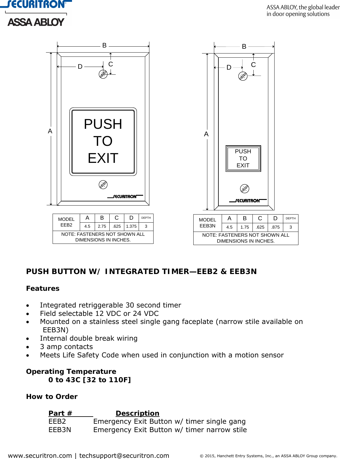
Push To Exit Button Wiring Diagram Diagram For You
The magnalock circuit design will automatically select the proper operational conditions for the applied voltage.

Securitron key switch wiring diagram. It smartly turns standard mortise cylinder into full featured key switch. The keypad and the cpu board connected by a 16 ft. With fully sealed electronics, it is recommended for exterior and perimeter doors.
If the lock is connected with reverse polarity, it will not operate. Key will operate the switch when turned in either direction. Securitron mk series ul listed mortise keyswitch with led.
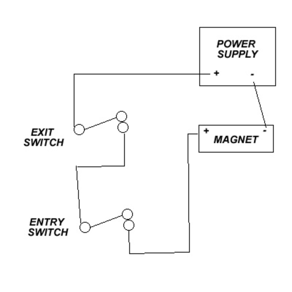
Additional switch position on backing bracket allows another switch. Wiring the electromagnetic locking system. A second switch ordered separately can be affixed to the unit so that turning the key left will depress one switch and turning it to the right will depress the other.
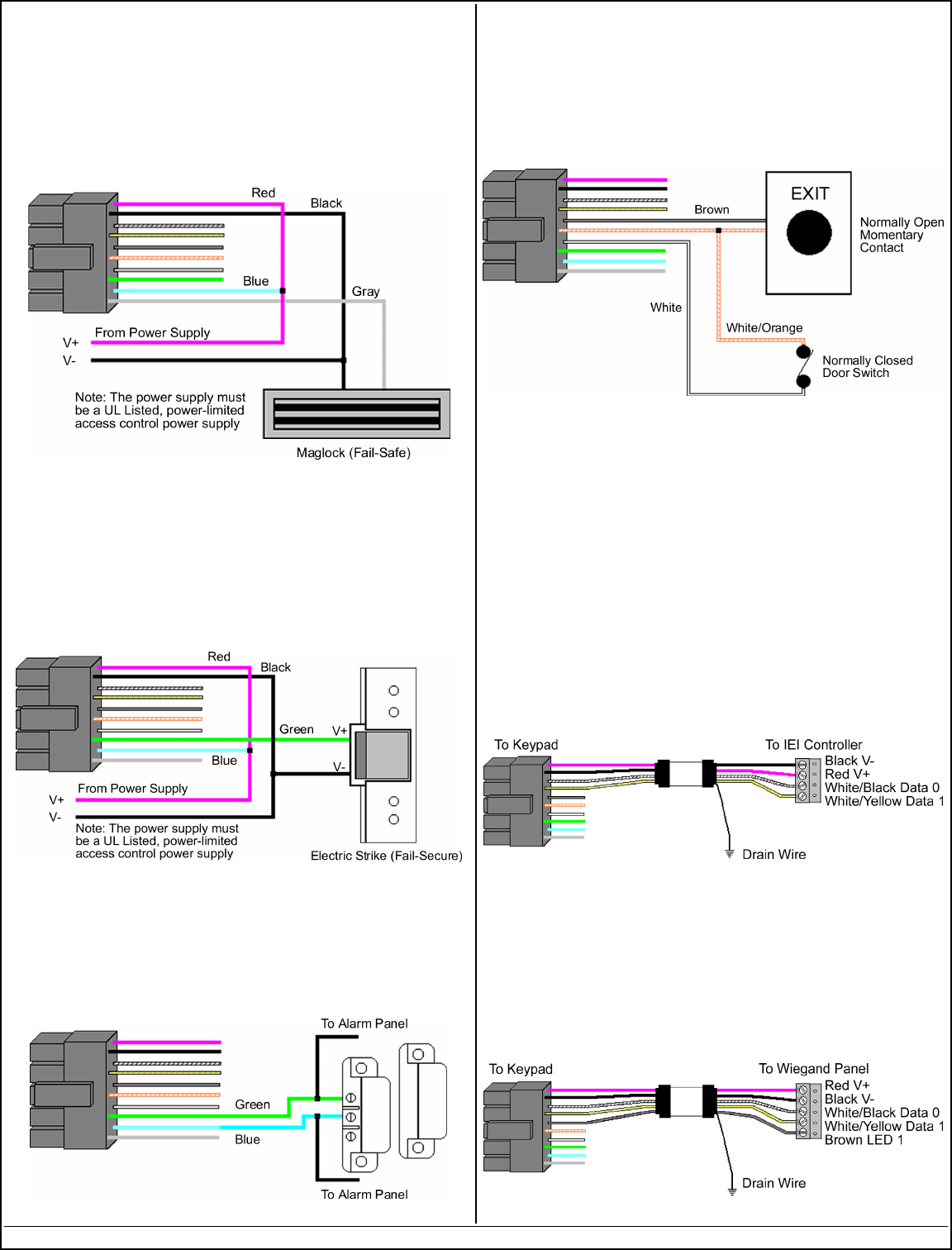
Momentary and alternate switches may be combined on the same unit. Turn standard mortise cylinder into into full featured keyswitch. The following reference sections provide installation documents and wiring diagram schematics for maglocks.
It shows how the electrical wires are interconnected and can also show where and how components are connected to the system. In the simple diagram above, you can see that the electricity travels in an unbroken loop. The securitron m62 magnalock offers 1200lbs of holding force and automatic dual voltage.
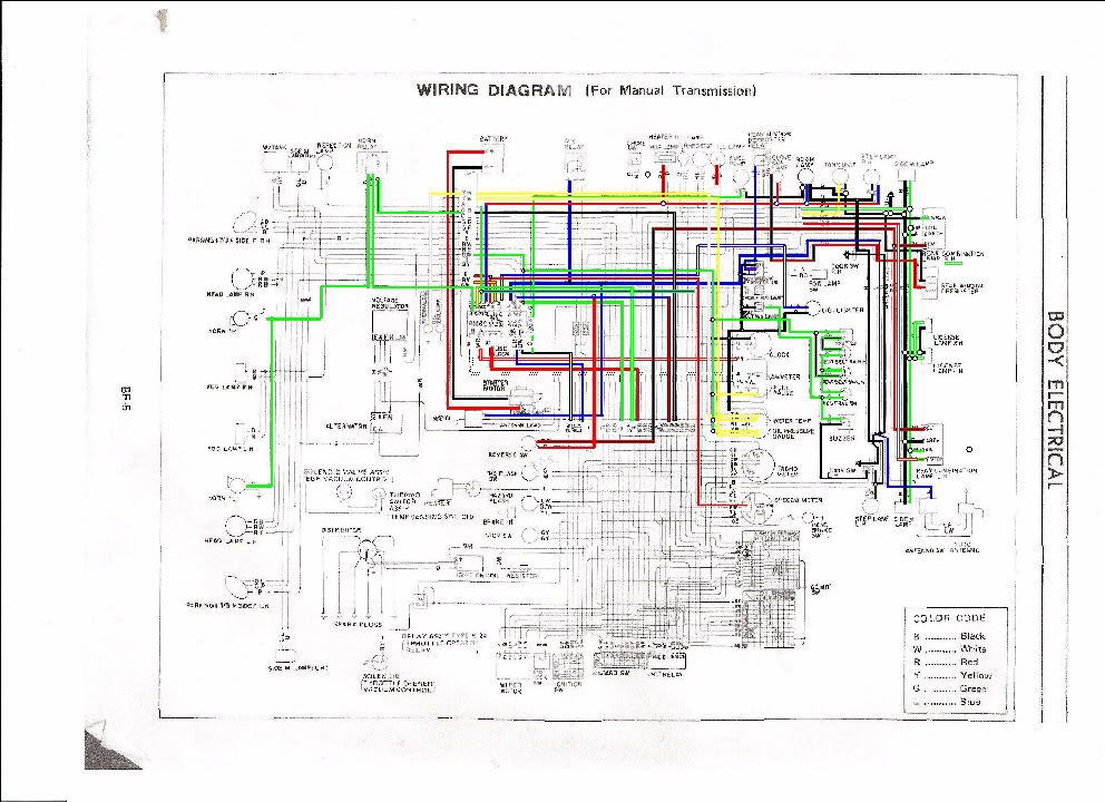
Code wire colour code wire colour b black p pink br brown r red g green sb sky blue gr gray si silver l blue v violet lg light green w white o orange y yellow if a cable has two colours the first of the two colour code. The securitron mka is a single gang alternate action spdt mortise keyswitch that turns a standard mortise cylinder into a full feature keyswitch. Momentarily turning the key changes the state of the contacts.
The securitron mk mortise keyswitch offers an additional switch position on the backing bracket allowing another switch to be activated by turning the key in the opposite direction. Both eeb2 and eeb3n have a 3a. Key card switch wiring diagram.
They come in a variety of shapes and sizes and are designed for monitoring door positions, roof hatches, gates, and more. The following common wiring diagrams are available. Securitron is the leading manufacturer of electromagnetic locks, access control components, power supplies and accessories.
It consists of two components: Model eeb3n is a rectangular exit button, mounted on a 1 3/4" s.s. Key removes when cam is in down position switch 1 1/8 or 1 1/4 any cam green led wire red led wire black led wire (note resistors)
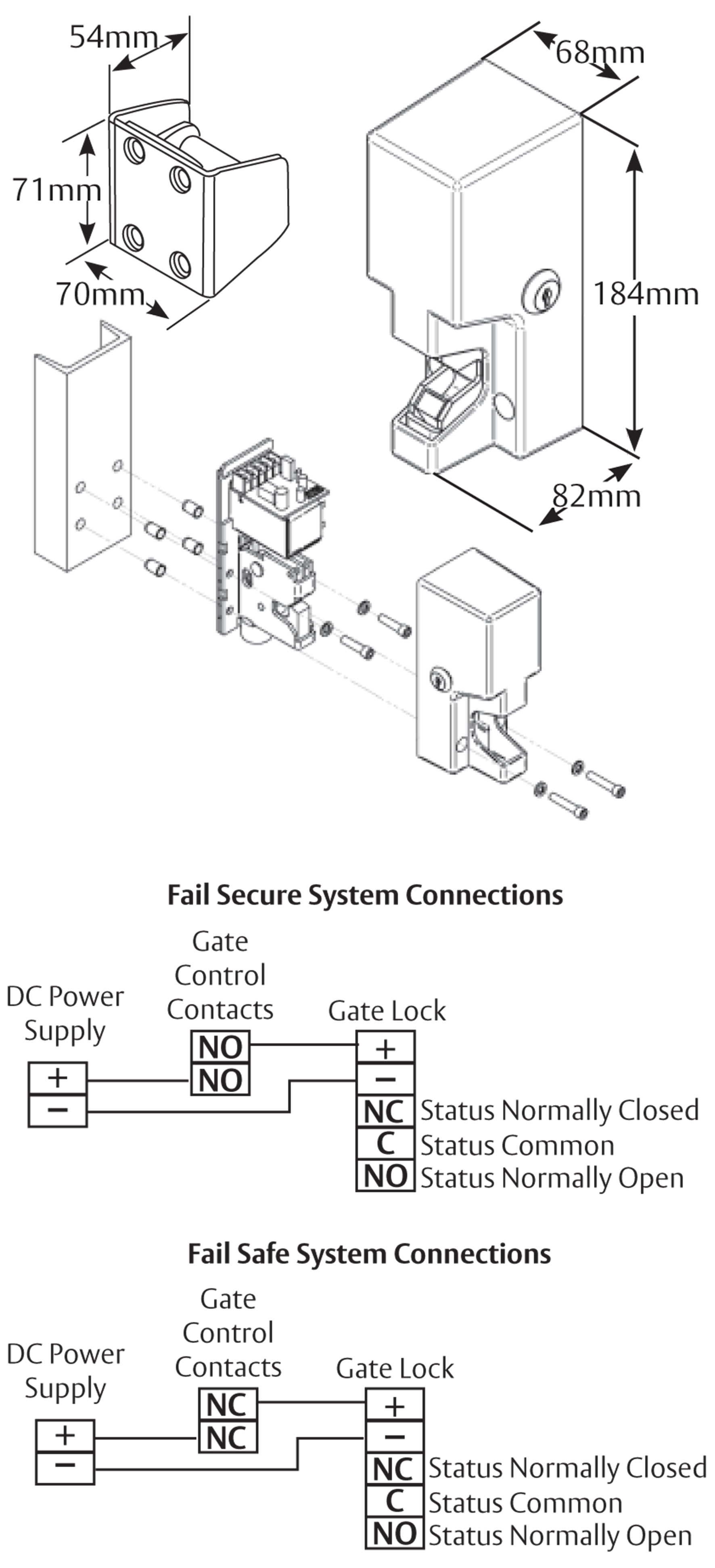
The switch signals the use of the opening to security systems. If this is not available you may use an ac power source an d wire inline a "full wave bridge" rectifier. Rex characteristics holding the rex switch closed will keep the lock released.
The m32, m62 and m82b magnalocks are auto sensing dual voltage locks. A wiring diagram or schematic is a visual representation of the connections and layout of an electrical system. The following common wiring diagrams are available:
Delayed egress x dk11 x bps: Deed delayed egress wired to release both exits when one goes into alarm: Red wire receives +12vdc or +24vdc, and the black wire, 0 volts (negative).
The mov absorbs this high voltage spark and therefore greatly prolongs the life of the control relay or switch. To order extra switches, the securitron part number for a momentary switch is mks. For less demanding applications, 2 keys included.
When in toggle mode the rex switch will toggle the relay state. Then lock the switch in position with the locking nut hardware. You must experiment with the switch mounting position to be sure of consistent function.
Wiring Diagram To Maglock Iei Keypad Wiring Diagram Schemas
Denny's M62B44 swap (MS2 installed First start VIDEO inside) Page 7 R3VLimited Forums

Acces Wiring Diagram
Push To Exit Button Wiring Diagram Wiring Diagram

Acces Wiring Diagram

73 240z Pertronix Ignition Wiring Diagram
Basic Door Lock System HubPages

Push To Exit Button Wiring Diagram Free Wiring Diagram
73 240z Pertronix Ignition Wiring Diagram

Wiring Diagram To Maglock Iei Keypad Wiring Diagram Schemas
73 240z Pertronix Ignition Wiring Diagram

13 Awesome Securitron Key Switch Wiring Diagram
13 Awesome Securitron Key Switch Wiring Diagram

Push To Exit Button Wiring Diagram Diagram For You
Pertronix Ignition System Wiring Diagram Gm Wiring Diagram

Hardware Direct Securitron GL1 900kg Electromechanical Gate Lock

Securitron Request To Exit Button

13 Awesome Securitron Key Switch Wiring Diagram
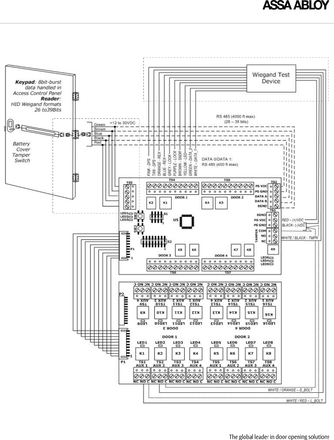
Securitron WTMN1A_24SEP08 WT1 Wiring And Use Instructions I 500 63020 A